Copyright © 2007 - 2025, Coachworks For contact data Click Here.
Copyright © 2007 - 2025
Copyright © 2007 - 2025,
Coachworks For contact data
Click Here.
![]() has been retained for reference purposes.
has been retained for reference purposes.
 Porsche
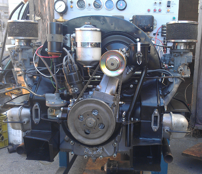
Engine (sold):
Porsche
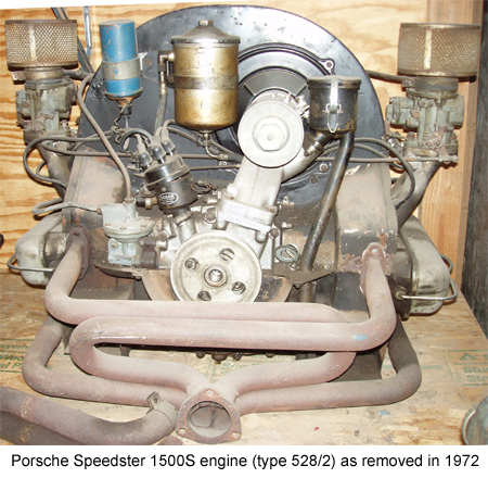
Engine (sold):Delivered in a 1955 Speedster in the San Francisco Bay Area, this engine was out of the vehicle in 1972 being serviced by a then-young Harry Pellow, having its Hirth roller-bearing crankshaft serviced by (we presume) Harry's friend Jim Wellington, when the Speedster was stolen.
With no original Porsche to be returned to, the engine was then installed in a Beetle Cabriolet, whose hapless owner failed to adjust the clutch following installation, and within months, the now clutchless engine was sold and installed in a 1960 Karmann Ghia Cabriolet. The Ghia owner, being clueful, replaced the clutch but after only driving it "around the block a few times", decided the Ghia needed restoration, so the engine and Ghia sat in a private garage until I bought the Ghia circa 1990. I ran the engine at that time, measured the oil pressure at temp and listened to it; it passed the inspection. I removed the engine and sold the Ghia shortly thereafter and the engine has remained on my engine shelf until recently when the rebuild process began.
 My
interest in the engine was primarily the Hirth crankshaft. At that time I needed
one for a 1954 1500S, but by luck found a new one, so this engine remains essentially
complete as it was when it entered my hands.
My
interest in the engine was primarily the Hirth crankshaft. At that time I needed
one for a 1954 1500S, but by luck found a new one, so this engine remains essentially
complete as it was when it entered my hands.
Harry Pellow, "The Maestro", had rebuilt this engine just prior to it having sat for all these years, with very little use in service after completion. So, I expected it to be in great condition, and it was. However, I have attended to a lot of things Harry failed to attend to - such as replacing all the valve guides, a couple of valve seats (which were "brass"), facing the lifters, and so forth. Its been completely rebuilt this time.
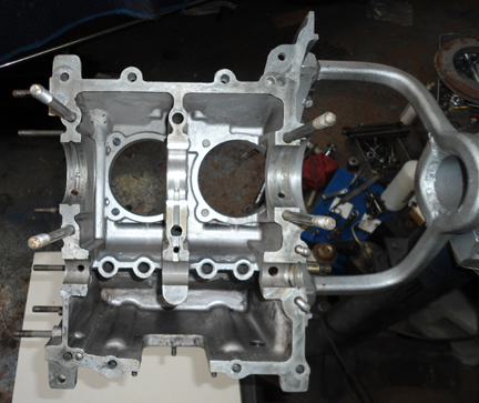
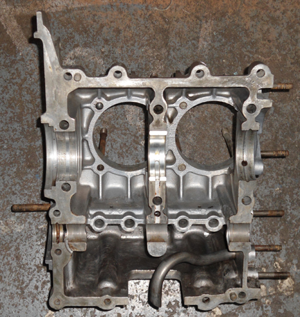
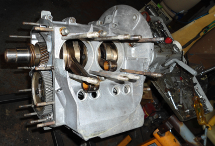
After dismantling the engine, I cleaned the crancase, bolted it back together and measured it: It's a fine standard size.
Here are some images of the crankcase:
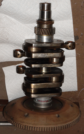
I then checked out the crankshaft. Aside from knowing some of the history, the spec. book does contain information on how to know if the crank is otherwise reuseable (you check the arc proscribed by the rods). Again, it's in fine shape.
Next up, set the end play with the new bearings:
Harry had neglected to reface the lifters - they weren't bad, but I went ahead and did them anyway.
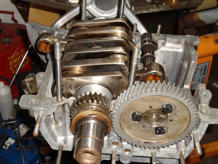
The cam was and is in great shape. Notice in the pictures below how little wear (as in ZERO) at the oil pump drive slot.
Here's the crankcase going back together. Note the original part number on the end of the cam, written in ink! This was possibly a new cam when Harry reassembled it. (Remember, in his own words, back then he was "not yet the Maestro" - should have faced those lifters!)
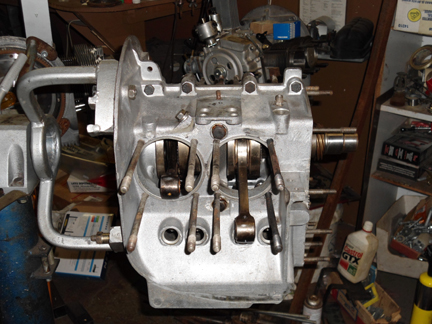
And, using copper sealing washers, as original, here it is with the bottom end waiting for the timing cover:
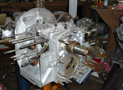
And from either side - pretty nice crankcase....
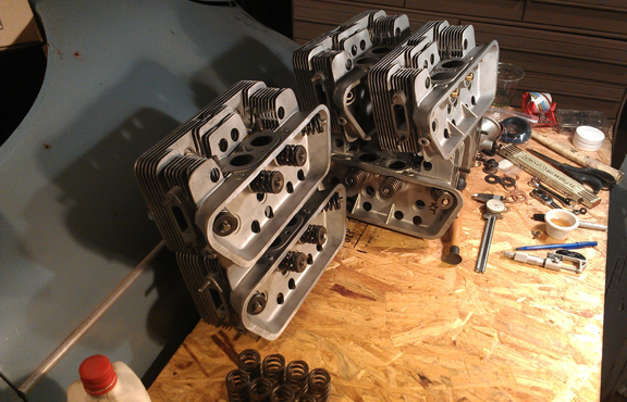
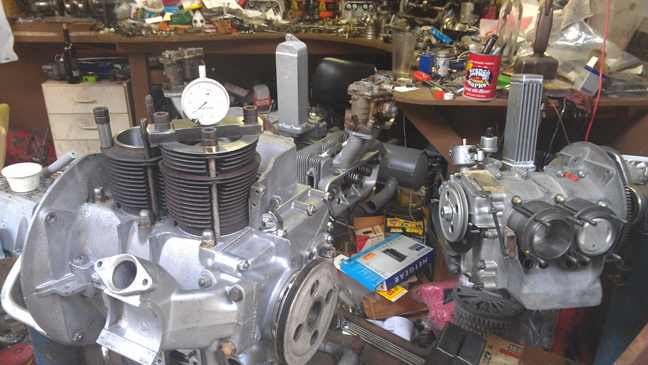
I was working on three engines at the same time and did all six heads together "as a batch" - saves a little time getting all the tools out. I didn't think to take images of each during the work, so here the images are. . . The three pair: 912, "C", and the heads for this early three piece case Super. (Can you pick out which are which?!)
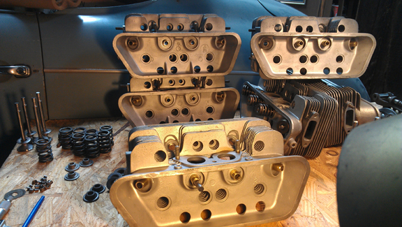
Yes, that's one of the heads for this engine in the foreground. Its mate is top right.
Here, the spring heights are being set. Previously, the springs were measured and very close sets matched up, so all have the closest possible spring tension. Each valve and retainer are position-specific...
I wish the detail of the valves and such were more vivid in these smaller images - in the full-size images you can really see the glistening, freshly refaced valves, polished stems, and, of course, it's a lot more obvious that all the guids here are new...
OK, time now to do a little more on the crankcase... It goes pretty quickly at this point.
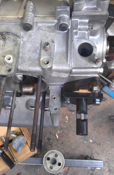
Almost immediately, the timing cover and its various accessories are mounted and the fuel pump pushrod gets adjusted.
Note the use of the factory fuel pump tools - they come as a set of two. We have virtually all the factory tools and use them!
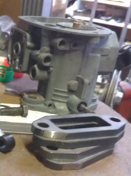
Here we see the one being used for the pushrod depth adjustment. (Unfortunately, it didn't occur to me to photograph using the other one when installing the fuel pump's diaphram into the pump housing.) Below, note that adjustment is accomplished by adjusting the number of gaskets between the pump and the spacer block. In this case two were required.
Time to install the Pistons and Cylinders. Note that Harry Pellow had apparently replaced the original chrome-plated aluminum cylinders with NPR Big-Bore pistons and they were run WITHOUT the now traditional 1mm shims under the cylinders. There were some impressions in the heads from the piston crowns and while the heads were unaffected, I didn't trust the pistons for not being cracked.
The proper 80mm bore piston and cylinder is very rare. The piston is identical to the earlier 1500S, however the cylinder is different. You can read more about the cylinder here. I do happen to have the cylinders, though the hard-chrome they're plated with has worn through, so they need either replating or relining with iron, which will do at added cost. The pistons I do not have, though I can have them made, just as I have made many other rare pistons.
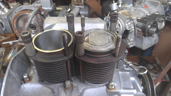
So, I dug into my stash and pulled out a very rare set of 1600S pistons and cylinders intended for the roller-bearing crankshaft. They can be positively identified by: The bore is 82.5, they are short-skirt style, they have a crown (are not flat-topped) and they have two 3mm compression rings and one 5mm oil control ring. Oh, of course, these were balanced as a set before installation.
Here they are below, installed, with new Grant brand rings.
Time for the cylinders - honed and ready.
For the curious, and to see those glorious S pistons close up, here's a closeup!
At this stage, many would just slap on the heads and call it done! However, we're more careful than that.
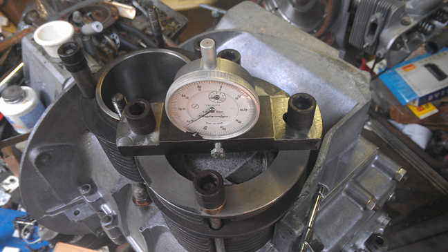
Here's where experience and superior tools come in! There are errors all over the place in the manufacturing process. Well, we like to catch what errors we can find and due to some perplexing issues we've found in the past, we've made our own tooling to help do a better job, faster. Here, we measure the height at which each individual piston protrudes from each cylinder. This helps us ensure a perfectly balanced engine and avoid any unseemly assembly errors!
Here's a closeup so you can see what's actually happening.
Now, we combine this data with the combustion chamber volume data we obtain from CCing the heads, and then shim the cylinder bases accordingly.
At this point, which head fits on which side is decided, and the shimming of the cylinder bases completed, and finally the heads are mounted.
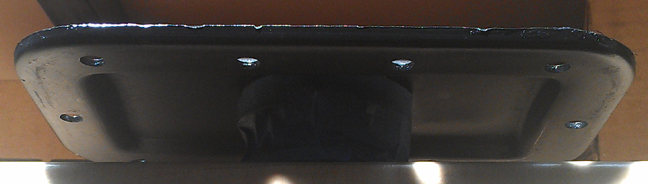
However, at about this point it was time to close up the oil sump - I often leave it open until the cylinders are finished to handle the unlikely occurance of a pin circlip falling into the engine during piston installation. I thought maybe it would be good to show the quality of these unmolested, original parts. Note that the sump screen isn't all mangled up but is actually in very nice condition.
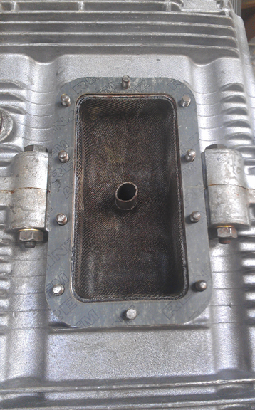
Similarly, note how the sump plate isn't distorted from over-torqing of its M6 retaining nuts! (Note, the proper torque is only 6 foot pounds.) Here, it's getting a little coat of paint to protect it in the future, but I didn't try to fix any of the minor dings. Covered by the masking tape is the magnet - it's the early one, as also used in the two-piece case engines.
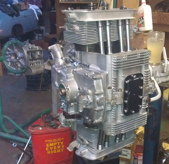
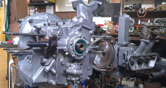
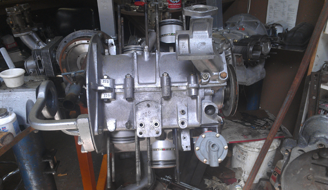
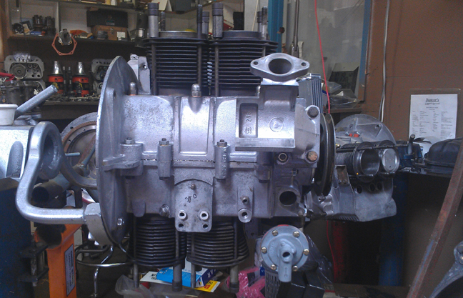
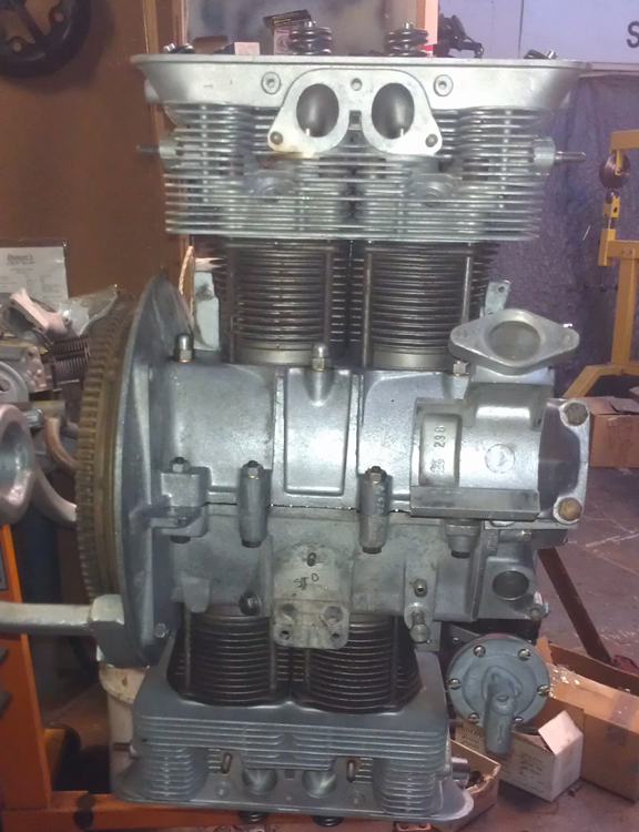
At this point, here's the longblock - plus a few accessories (fuel pump, generator stand, dip-stick tube), and minus a few bits (rocker arms, valve covers:
Many of the little pieces have been undergoing some form of restoration all the while - I just didn't document all of it. (Do you really want to see the fan shroud being cleaned?) Some of the pieces required more attention than others, and they're called out below. Some bits, like the flapper boxes and cylinder tin got powder-coated. The platers didn't get their work done in time, and I had to put it together without all the freshly plated parts I had planned! This I found very annoying, especially regarding the carburetors...
Speaking of carburetors - the carburetors are the original pair, and they're in great condition. Here they are after being dismantled for rebuilding, but before reassembly has begun:
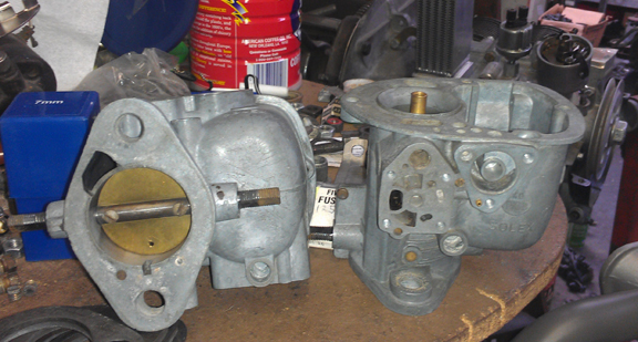
I happened to catch something interesting in this next photo. I've never noticed this in a Solex carburetor before, but it's a great way to cure throttle-shaft leak problems. Note the blank space around the shaft, between the shaft and the casting. There were o-rings in these spaces, discovered upon disassembly. Hmmm... There are no o-rings supplied in the rebuild kits! (Note that we use the metal plates in the foreground to make custom exhaust systems. You can see an example of our work here.)
Speaking of things that aren't in the rebuild kits, this particular pair uses a triangular diaphram that's not used on all versions of this carburetor as delivered by Porsche. Though the parts manual denies this, and though the standard (Stoddard-supplied) rebuild kit S0-5K (616.08.902) does not include these, we have seen enough of these on Porsche engines that have come our way that we're sure they're original. Thankfully, there are both 32 and 40 Solex carburetor versions that use the same triangular diaphram, so they're a little easier to come by than hen's teeth. Here's the old and new pairs:
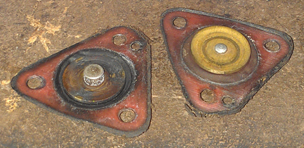
Note that in each image both sides are shown, one up, one down.
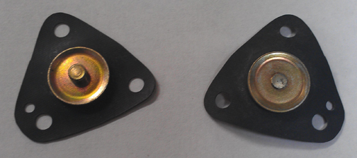
Also note that the extra hole, not in a corner, is present to ensure the diaphram is only installed the correct way.
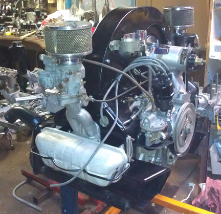
At about this point, it became more important to "button it up" and finish the engine than to take time documenting the work. So, I didn't take many images during this phase, and it looks as though we just jump ahead to a nearly completed engine! Then, as if by magic, it's completed!
Almost right away, the rocker arms got mounted and valve covers installed. Then, the heater boxes were mounted and J-tubes installed, along with the upper cylinder tin. Then, the carburetors were mounted. This literally took barely an hour, if that! The generator strap was slid onto the generator, the generator was mounted to its mounting plate, then to the fan shroud, and then the fan shroud was installed. Then the accessories to that were installed, such as the throttle linkage, oil filter mounting bracket, fuel line, and so on.
One thing that took a bit of time was the oil filler / breather in that the down-tube required "straigtening" - well, not so much making straight, but it needed to be fitted so it didn't exert any pressure whatsoever on the plate it has to go through on its way exiting the engine bay. So many times this is NOT done and the end result is that the horizontal sheet metal cuts through the breather tube via vibration in service. It took a LOT longer than I'd have thought, and it helped VERY MUCH that I had another engine case near by with a generator stand mounted so I could tweak the piece as necessary without having to dismantle the sheet metal each time in order to gain room to do the tweaking.
At this point, I realized I hadn't taken many photos, so I snapped a few shots.

One thing worth noting here is the detail of the oil system. Firstly, it's rare, and there aren't too many images of this around. So, first, an intermediate close-up:
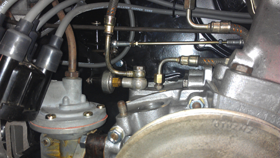
Note the banjo bolt goes through two fittings, and three sealing washers, then into the crankcase. Yes, it's 14mm across the flats. And note that nearly everybody uses copper sealing washers, but I don't because they don't work very well - use aluminum if you can get them! ALSO NOTE, you can re-use sealing washers! If necessary, flatten them on a sheet of very fine emory cloth, and also optionally anneal them, by getting them hot and letting them cool slowly - like, say in your kitchen oven...
Now, because you can't see it all that clearly here, just to prove how original this all is, in this next image, notice the date stamp on the oil pressure switch:
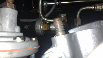
Yes, it reads "55" - it's the original oil pressure switch for this engine!
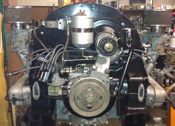
One part that was VERY difficult to get right was, of all things, the balance tube between the two carburetors. This part is unique to the single-barrel Solex 40 carburetors and their manifolds.
Firstly, I was lucky to have the correct boots because they were out of stock at Stoddard and every where else looked. But I bit the proverbial bullet and took a pair out of my personal stash (and hoping I can replace them)! Secondly, when I tried to install them I found the balance tube was bent somehow and refused to fit! I cannot imagine how it got bent. I cannot imagine how someone got the old boots intalled! However, I recall vividly taking the old boots off, so they WERE fitted! There was just No Way the parts were going to go back as they should. And, being a curved tube, it's very hard to "tweak it" into the correct position! You need specially sized tools to "do it right", I think. But with only one to do, I just took my time and did what I could. In the end, it helped very much to heat the rubber boots in boiling water in order to get them to stretch onto the fittings and into place. Whew! There were moments when I thought it just wasn't going to go together properly, but it did.
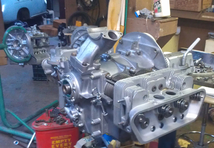
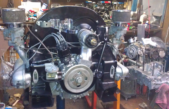
You can see the result in the image below.
You can also see in this image that, as I realized only later, this wasn't quite the right fan shroud as it should not have the bracket (on left in image, just inboard of the carburetor) for the engine thermostat! Oops! I could have cut it off at this point, but I figured I'd leave that to the new owner, who may have other plans.
Oh, and yes, that's an original fuel line!
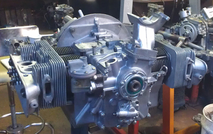
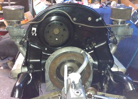
At this point the engine was sold, so it was dismounted from the engine stand and mounted up to the dynamometer, thus:
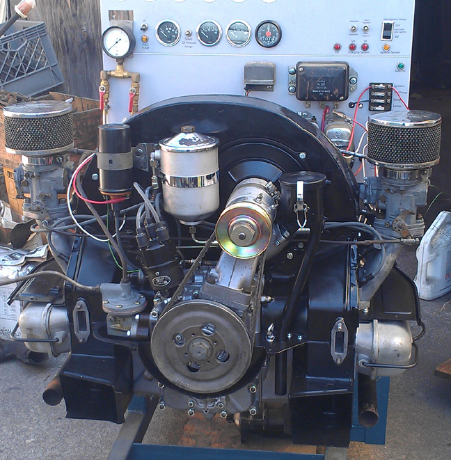
However, before I could mount up a muffler and fire it up, the new owner came to pick it up, was in a hurry, and didn't care about test running it, adjusting the timing, carburetors, and so forth. So I never got to hear it run! All that work and no satisfaction of running it again! Rats! Oh well, it's going to serve a long and happy life somewhere out there! At least it's supposed to be going into the correct car!
When you're ready for work on your machine, just let us know.
Because some people are keeping logs of VIN and engine numbers and then purport to tell people what someone else has, out of respect and concern for a buyer's privacy, exact VIN and engine number data is not published here.